Space Blanket Thermal Analysis
Closed-system thermodynamic modeling and experimental validation of thermal blanket insulation. JWST sunshield samples provided by NASA Goddard Space Flight Center.
Overview
A thermodynamics macroproject investigating the insulation performance of aluminum foil as a thermal blanket surrogate. A custom pressure vessel was built, heated by a 250 W lamp, with temperature measured via thermistor and Arduino pipeline. Results were compared against a first-law steady-state analytical model.
Project Specs
- System: Sealed cylindrical pressure vessel (milled tube body, lathed and welded end caps), thermistor + Arduino data pipeline
- Primary goals: Build an analytical steady-state model, validate experimentally, and compare a control (no foil) case against an analyzed (foil-wrapped) case
- Project artifacts: Analytical model, experimental temperature-time data, percentage error analysis, poster presentation
Introduction & Background
Thermal blankets act as near-perfect insulators for space-grade hardware, protecting components from thermal stress during cycling and the cold ambient conditions of space. The theoretical ideal is an adiabatic boundary: a surface that permits no heat exchange and, in the absence of work, produces no temperature change. Space-grade blankets such as the JWST sunshield approach this ideal closely. This experiment uses aluminum foil as a placeholder thermal blanket to quantify how much a reflective insulator reduces steady-state temperature compared to a bare surface.
System Construction
The vessel was built to isolate the body's temperature as much as possible. A tube body was milled, end caps were lathed and welded to the main body, and the thermistor jig was epoxied in place for a tight heat seal. A pressure relief mechanism was implemented via calibrated epoxy: calculations showed the internal pressure rise would remain near 1 atmosphere, a manageable safety margin. The final setup maximized surface area in contact with ambient air to promote convection, suspended the lamp independently to avoid radiation loss to supports, and removed the “heat chamber” effect seen in earlier iterations.
Analytical Model
Starting from the first law of thermodynamics for a closed system at steady state, with no work term and negligible end-cap conduction, the governing equation is:
0 = Q_rad-in − (Q_conv-out + Q_rad-out)
The 250 W lamp output is scaled by absorptivity α (since the system is not a perfect blackbody). Convection is modeled via Newton's law of cooling; radiation output follows the Stefan-Boltzmann law. The only unknown is steady-state body temperature T_b.
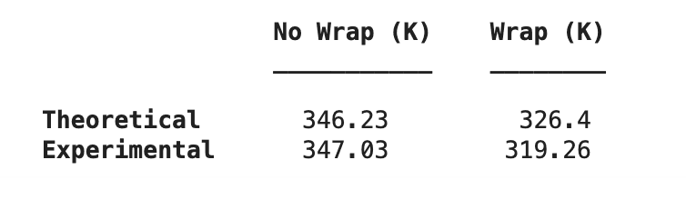
- Control case (α = 0.07): theoretical T_b ≈ 346.23 K
- Analyzed case (α = 0.02): theoretical T_b ≈ 326.4 K
- Ideal adiabatic: T_b = room temperature (~297 K)
Key assumptions: lumped body, steady state, negligible internal convection, constant room temperature, negligible conduction through end caps, no radiation from surrounding objects.
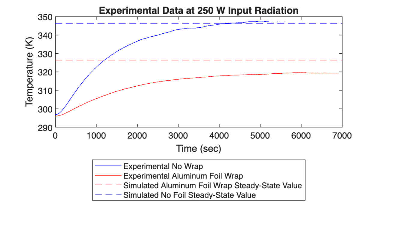
Experimental Results
Data collection ran for approximately 5 hours total, with each trial lasting ~1 hour and a ~45-minute cool-down between trials. Results corroborated the hypothesis: the foil-wrapped vessel reached a steady-state temperature significantly closer to the ideal adiabatic rest temperature than the bare control vessel.
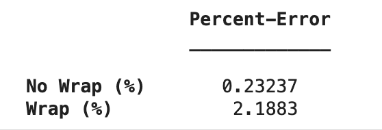
- Experimental control (no foil): T_b ≈ 347.85 K | percentage error vs. theoretical: 0.23%
- Experimental analyzed (foil): T_b ≈ 319.20 K | percentage error vs. theoretical: 2.19%
The analyzed case landed slightly below the theoretical prediction, likely due to a drop in room temperature (AC activation) mid-trial. Both percentage errors represent a one-order-of-magnitude improvement over prior experimental iterations.
Error & Uncertainty
Sources of uncertainty include measurement tolerances on area values and approximated material properties, as well as model simplifications (lumped body assumption, no internal convection, negligible end-cap conduction). Real-world deviations included ambient room temperature shift mid-trial and incomplete lamp coverage of the vessel surface. Future iterations could use lower-conductivity supports and constrain vessel dimensions to match the lamp's radiation footprint.
Project Media
Documents
Tools & Methods
Mechanical fabrication via manual milling and lathe work, welding, and epoxy sealing. Data acquisition through thermistor and Arduino pipeline. Analysis and plotting in MATLAB. Modeling based on first-law thermodynamic equations combining convective and radiative steady-state heat transfer.